

Trajectory simulation in laser clay is a software-driven recreation of a clay’s angular flight path that reproduces the visual timing and lead a shooter would experience outdoors. Rather than tracking absolute metres, the system models the angles and angular speed the clay presents to the shooter, then computes a measurable “aiming error” at the moment of closest approach, reported to the nearest centimetre. That single metric is what makes laser clay genuinely useful for training and research, not just entertainment.
- The simulation generates a target that follows the same angular trajectory and angular speed as a real clay
- Shot results are computed by comparing the centre of the shot pattern to the clay at the point of closest approach
- Feedback is delivered as two orthogonal distances: ahead/behind and left/right of the clay
- Systems such as DryFire report these as numeric errors (for example, 0.30 m ahead, 0.54 m left) alongside a shot-pattern visualisation
Table of Contents
- What is trajectory simulation in laser clay, and how does the model work?
- What hardware and software does a laser clay system need?
- Where does fidelity break down, and how do you manage it?
- Why is trajectory simulation valuable for training?
- How does DryFire implement trajectory simulation?
- How do you evaluate and set up a trajectory simulation system?
- A short calibration and test protocol for practitioners
- Key takeaways
- When simulation is the right choice, and when it is not
- Laserclay: a ready-made laser clay experience
- Useful sources and further reading
What is trajectory simulation in laser clay, and how does the model work?
The physics engine at the heart of any laser clay simulator does not simply move a dot across a screen. It solves a kinematics problem: given a trap angle, launch speed, deceleration profile, and optional wind parameters, where is the clay at every millisecond of its flight, expressed as azimuth and elevation angles from the shooter’s position?
Angular modelling matters because that is what the shooter actually perceives. A crossing clay at 30 metres and a crossing clay at 20 metres present very different angular speeds even if their linear speeds are identical. By working in angular coordinates, the simulator preserves the visual relationship between shooter and target, which is the variable that drives instinctive lead. Simulate in absolute metres and you lose that relationship the moment the projection distance differs from the outdoor range.
Beyond the clay’s position, the model must account for the shot itself. DryFire’s system computes shot placement using cartridge details, choke, muzzle velocity, target distance and wind parameters to estimate pellet energy and whether the clay would break at the computed intersection. The pellet cloud is modelled as a spatial distribution, not a single point, so the system can report a hit probability alongside the aiming error rather than a binary hit/miss.
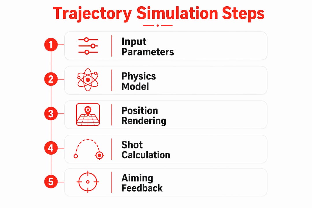
The full processing chain runs like this: input parameters feed the physics model, which renders the target’s position frame by frame. When the shooter pulls the trigger, the gun unit emits a pulse, cameras timestamp the event, and the registration module computes the point of closest approach between the modelled pellet cloud and the clay. That geometry produces the aiming-error figures the coach reads on screen.
Pro Tip: Set the trap angle and target speed to match the specific stand you are training for, not a generic crossing target. The angular speed at the hold point is what determines perceived lead, so even a small change in trap angle shifts the drill meaningfully.
What hardware and software does a laser clay system need?
Understanding the components helps you evaluate whether a given system can actually deliver the trajectory fidelity it claims.
Essential hardware:
- Projector or laser heads: render the clay’s simulated flight path on a screen or arena surface
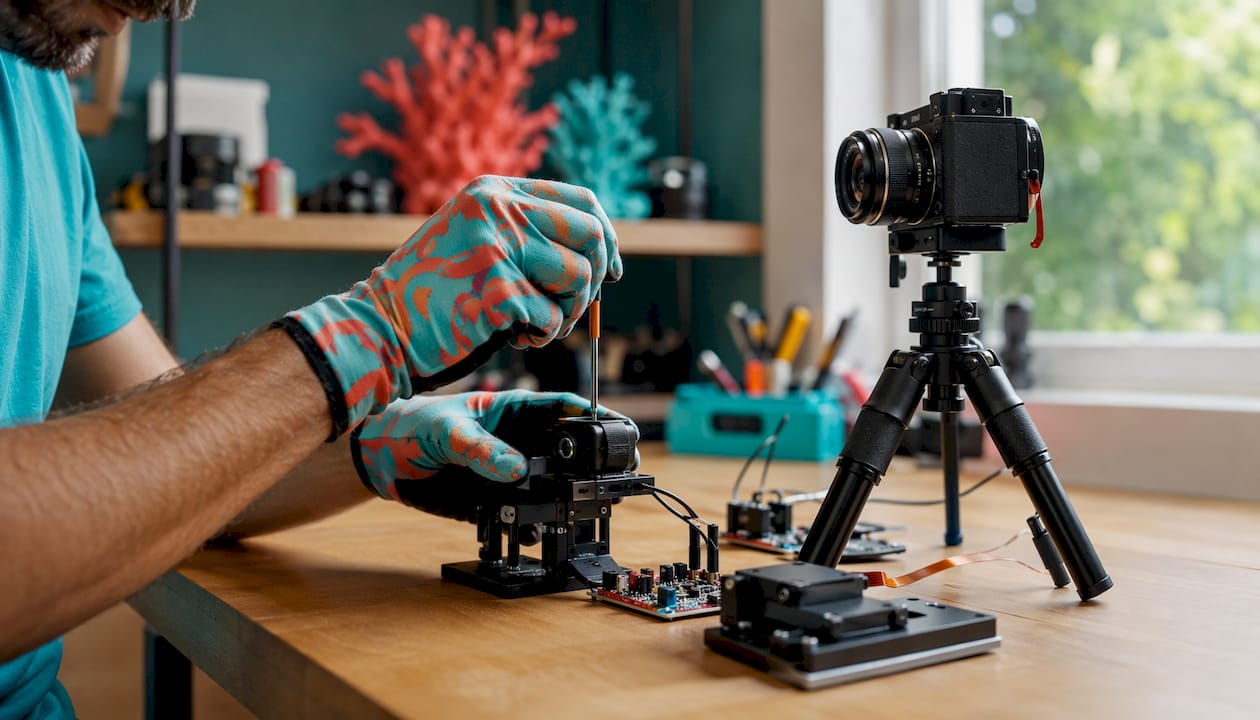
- Gun-mounted unit (UGA): clips to the barrel and emits a short pulse of invisible infra-red light when the trigger is pulled; DryFire’s UGA emits approximately a 1/30th-second pulse that the cameras detect as a reflected spot
- Camera heads: positioned to cover the screen; they detect the reflected infra-red spot, timestamp the event, and feed the data to the registration software
- Screen or arena: the projection surface; its size and distance from the shooter determine the angular range the system can reproduce
- Optional barrel-motion sensors: track the gun’s swing speed and direction, enabling barrel-trace overlays in the analytics
Core software layers:
- Physics and trajectory engine: solves the kinematics model and renders the clay’s angular position at each frame
- Shot-registration module: receives the camera timestamp, computes the point of closest approach, and calculates aiming error and hit probability
- Visual renderer: displays the clay, its flight path, and optional fragment behaviour on the projection surface
- Analytics and reporting layer: stores shot patterns, error metrics, and timeline playbacks for post-session review
In real time, the data flow is tight: trigger pull → UGA emits infra-red pulse → cameras detect reflected spot → software timestamps the event → registration maths compute closest approach relative to the simulated clay trajectory → feedback appears on screen within the same session. Synchronisation between the UGA and cameras is typically handled over Bluetooth or a wired link, and any timing jitter in that handshake is one of the primary sources of measurement error.
When the shooter stands fairly close to the projection wall, the simulator can display the complete trajectory from trap to ground because the angular equivalence with outdoor movement is preserved at that distance. DryFire’s setup guidance confirms this: close, controlled projection distances are what maintain angular fidelity across the full flight arc.
Where does fidelity break down, and how do you manage it?
No simulator is a perfect replica of outdoor conditions. Knowing where errors enter the system lets you calibrate expectations and design training sessions that stay within the system’s reliable range.
| Error source | Typical effect | Practical mitigation |
|---|---|---|
| UGA timing jitter | Angular position error at the moment of shot; translates directly to aiming-error bias | Use wired sync where available; run a static latency baseline test before each session |
| Camera sampling rate | Missed or interpolated shot timestamps; increases variance in repeated trials | Use cameras rated for the system’s specified frame rate; avoid mixing hardware generations |
| Model assumptions (simplified pellet spread) | Hit probability figures may be optimistic for tight chokes at distance | Enter accurate choke and load data; treat hit probability as indicative, not absolute |
| Ambient light interference | Camera false-triggers or missed detections | Shoot in controlled lighting; cover windows and avoid direct sunlight on the screen |
| Reflective surfaces near the screen | Ghost reflections confuse camera detection | Use matte screen material; remove or cover nearby mirrors and glass |
| Projection distance variation | Angular speed mismatch if the shooter moves significantly from the calibrated position | Mark the shooter’s position and enforce it during measurement sessions |
High-end systems such as DryFire report aiming errors to the nearest centimetre under ideal calibration, but that figure assumes accurate parameter entry and a controlled environment. In a typical club setting with variable lighting and approximate choke data, expect slightly wider variance. The number is still far more informative than a simple hit/miss signal; it just needs context.
Pro Tip: Run a static shot-registration check at the start of every session: aim at a fixed point on the screen, fire five shots, and confirm the reported positions cluster within your system’s specified tolerance. If they do not, recalibrate before using the data for coaching.
Why is trajectory simulation valuable for training?
The core advantage is repeatability. Outdoors, no two clay presentations are identical: wind, trap wear, and human loading variation all shift the target slightly. A simulator reproduces the same angular trajectory run after run, which is what deliberate practice actually requires. You can isolate a single variable, say the effect of a steeper crossing angle on perceived lead, and measure it across 30 identical repetitions without any of the noise that outdoor conditions introduce.
- Quantifiable feedback: shot-pattern displacement, aiming error in two axes, and barrel-motion traces give coaches objective data that verbal feedback cannot match; detailed analytics can reveal subtle technique issues such as early trigger pull or a twitch at the moment of shot
- Reaction-time drills: the system can vary the delay between target call and clay appearance, making it straightforward to run reaction time training with measurable outcomes
- Equipment testing: changing choke or load parameters in software lets a shooter compare theoretical shot-pattern performance without burning through cartridges
- Research applications: controlled repeatability is especially valuable when you need low-variance conditions to isolate a single variable, for example analysing how lead changes with varying target angular speed
- Safe indoor practice: no live ammunition, no lead contamination, no noise restrictions; sessions can run in spaces that would never accommodate a live-fire range
- Lower running costs: once the hardware is in place, the marginal cost per shot is negligible compared with cartridges and clay targets; practising without live ammo also removes the environmental burden of lead shot
For skill acquisition, the combination of identical repetitions and immediate numeric feedback accelerates the feedback loop that coaches rely on. A novice can see within a single session whether they are consistently behind the clay or consistently low, and a coach can quantify improvement across weeks rather than relying on subjective observation.
How does DryFire implement trajectory simulation?
DryFire is probably the most documented implementation of full angular trajectory simulation for clay shooting, and it illustrates the concepts above in a concrete, purchasable form.
The system models targets that follow the same angular trajectory and angular speed as real clays, then computes shot results by comparing the centre of the shot pattern to the clay at the point of closest approach. Two orthogonal error distances are reported: how far ahead or behind the shot centre was, and how far left or right. The software accounts for cartridge and choke parameters when modelling pellet behaviour, so the hit probability figure reflects the actual load rather than a generic approximation.
DryFire’s shot-registration module timestamps the trigger event using the infra-red pulse from the UGA, locates the reflected spot via its camera heads, and computes the aiming error at the moment the simulated pellet cloud is closest to the clay. The result is a numeric error value displayed alongside a visual shot-pattern overlay relative to the clay’s position at that instant. Optional gun-motion add-ons extend the analytics to include barrel-swing traces and timeline playback, giving coaches a frame-by-frame reconstruction of the shot.
The analytics layer is where DryFire earns its reputation among serious coaches. Shot patterns are stored session by session, so trend analysis across weeks is straightforward. The timeline playback shows not just where the shot landed but when, relative to the clay’s position, which is the data point that matters most for diagnosing lead errors.
How do you evaluate and set up a trajectory simulation system?
Choosing a system without a structured evaluation risks paying for hardware that cannot deliver the fidelity your training or research needs. Work through these criteria before committing.
Evaluation checklist:
- Trajectory fidelity: does the system model angular coordinates, or does it use a simplified hit-radius approach? Ask for the physics model documentation.
- Analytics depth: are two-axis aiming errors reported numerically, or only as a visual overlay? Numeric outputs are essential for coaching and research.
- Latency and sample rate: what is the camera frame rate and the UGA pulse duration? Lower latency and higher frame rates reduce timing jitter.
- Installation footprint: what minimum room dimensions does the system require, and can it be set up in your available space while maintaining angular equivalence?
- Calibration ease: how long does a full calibration take, and does the software guide the user through it step by step?
- Cost of ownership: factor in hardware, software licences, maintenance, and the cost of any consumables or replacement parts.
- Support: is technical support available in the UK, and what is the typical response time for calibration issues?
Acceptance test — run this before relying on the data:
- Attach the UGA to the gun and confirm the Bluetooth or wired link is active and showing a stable connection in the software.
- Aim at a fixed reference point on the screen and fire five shots; confirm the reported positions cluster within the system’s specified tolerance (typically a few centimetres).
- Run three identical slow-crossing targets and log the reported aiming error for each shot; compute the mean and note any outliers.
- Repeat the crossing-target run at a steeper angle and compare the variance between the two sets; a well-calibrated system shows consistent variance regardless of target angle.
- Check that hit probability figures change predictably when you alter the choke parameter in software, confirming the pellet model is active.
Pro Tip: Mark the shooter’s standing position with tape before calibration and enforce it during every measurement session. Even a half-metre shift changes the angular relationship between shooter and screen, which introduces a systematic bias into all subsequent aiming-error readings.
A short calibration and test protocol for practitioners
For coaches and researchers who need reproducible results, a structured calibration sequence is not optional.
Angular zeroing: with the gun held at a known reference angle (typically horizontal, pointing at a marked centre point on the screen), confirm the software registers the shot at that reference position. Adjust the camera-to-screen registration until the reported position matches the physical aim point within the system’s specified tolerance.
UGA latency baseline: fire ten shots at the static reference point in rapid succession and log the timestamps. The standard deviation of those timestamps is your latency baseline; anything above the system’s specified jitter tolerance indicates a sync problem to resolve before training data is collected.
Pellet-model parameter entry: enter the exact choke constriction, payload weight, and muzzle velocity for the load being simulated. These inputs directly affect the computed pellet distribution and therefore the hit probability output. Using default values when the actual load differs introduces a systematic error in every hit probability figure.
Short reproducible test protocol: run three identical slow-crossing targets, log the reported aiming error for 30 shots, and compute the mean and standard deviation. Repeat at a steeper angle and compare variance. High-quality systems show low mean bias and small variance between runs, as confirmed by DryFire’s own acceptance testing guidance. Log environmental conditions (lighting level, room temperature, any changes to reflective surfaces) alongside the data so that session-to-session comparisons are valid.
Why does angular modelling matter so much for transfer to outdoor shooting? Because the shooter’s hold point and the perceived lead are both functions of angular speed, not linear speed. A simulator that matches the angular speed of a real clay at the hold point produces the same visual stimulus the shooter would experience outdoors. That match is what drives transferable instinctive learning, and it is why the physics model is the most important specification to verify before purchasing any system.
Pro Tip: For research requiring low variance, run all trials within a single two-hour session rather than across multiple days. Room temperature, lighting, and even the shooter’s fatigue level affect variance; controlling session length is the simplest way to reduce unexplained variability in your data.
Key takeaways
Trajectory simulation in laser clay works by modelling a clay’s angular flight path and computing a measurable aiming error at the point of closest approach, giving coaches and researchers objective, repeatable data that live-fire practice cannot match.
| Point | Details |
|---|---|
| Angular modelling is the core | Systems simulate angles and angular speed, not absolute metres, to preserve the shooter’s visual relationship with the clay. |
| Shot registration uses closest approach | The aiming error is computed at the moment the modelled pellet cloud is geometrically nearest to the clay, reported in two axes. |
| Latency dominates small errors | Camera frame rate and UGA timing jitter are the primary sources of measurement error; run a static registration check before every session. |
| Run the acceptance test first | Before using simulator data for coaching or research, complete the five-step acceptance test to confirm calibration is within tolerance. |
| Laserclay for hosted experiences | Laserclay offers ready-to-use laser clay experiences that apply these principles in a safe, eco-friendly format for training and events. |
When simulation is the right choice, and when it is not
The case for simulation is strongest when you need something outdoor shooting cannot give you: identical repetitions, objective numeric feedback, and a controlled environment. For skill acquisition in the early stages, for coaches who want to quantify technique changes over weeks, and for researchers who need low-variance conditions to isolate a single variable, a well-calibrated simulator is genuinely superior to live fire. You can run 200 identical crossing targets in an afternoon indoors; you cannot do that on a trap field without significant cost and logistical effort.
The case for live fire is equally clear in other situations. Recoil management, the physical weight and balance of a loaded gun, and the full ballistic behaviour of shot at distance are things no current simulator fully replicates. High-speed environmental variability, such as a driven pheasant in a crosswind, involves sensory inputs that a screen simply cannot reproduce. For shooters preparing for competition at the highest level, simulation is a complement to live fire, not a replacement.
The most effective training programmes combine both. Use the simulator for deliberate, data-driven practice on specific technique problems, and use live fire to consolidate those changes under realistic conditions. The accuracy comparison between laser and real clay is worth reading if you want a detailed breakdown of where the two approaches converge and where they diverge.
Laserclay: a ready-made laser clay experience
If you want to experience high-fidelity laser clay without sourcing and calibrating your own hardware, Laserclay offers fully managed sessions that put these principles into practice. The proposition is straightforward: safe, eco-friendly laser clay shooting with no live ammunition, no lead contamination, and no specialist venue required. Sessions suit training days, corporate events, and research-friendly setups where repeatability and measurable feedback matter.
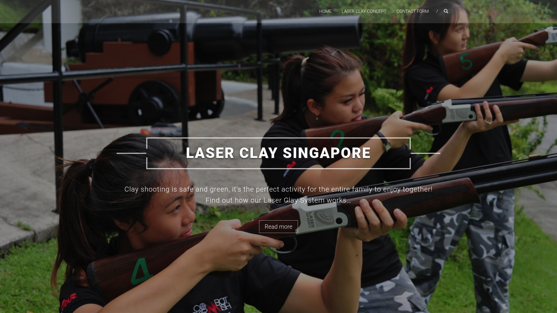
Laserclay’s format is accessible regardless of shooting experience, which makes it practical for mixed groups as well as dedicated training cohorts. The absence of live ammunition removes the cost and environmental burden of cartridges and clay targets, and the controlled setup means sessions can run in spaces that would never accommodate a conventional range. For event organisers, the safety profile alone simplifies logistics considerably.
To see what a session involves or to book a date, visit the Laserclay how-to-play page for full details on formats, group sizes, and availability.
Useful sources and further reading
- DryFire: how it works — the primary vendor documentation for DryFire’s angular trajectory model, UGA shot-detection system, and aiming-error reporting; the most detailed publicly available description of full trajectory simulation implementation for clay shooting.
- DryFire overview — covers projection distance, angular equivalence, and setup considerations; useful for understanding how room geometry affects fidelity.
- Visual Target Tracking in Clay Pigeon Shooting Sports — academic paper describing methods to estimate clay trajectory and flight distance by measuring early portions of a target’s flight and applying kinematic fitting; provides independent technical context for the trajectory modelling discussed in this article.
- Simulated game shooting — practical definitions of simulated clay and laser clay shooting for participants; useful background on how the activity is described to UK audiences.
- Laserclay: skill development guide — practical guidance on using laser clay for structured skill development, including drill design and progression.
- Laserclay: practising without live ammo — covers the practical and environmental case for simulator-based practice; relevant to coaches and facility managers evaluating the switch from live fire.